
 Expand Image

Since joining the faculty at Penn in 2017, Associate Professor of Architecture Masoud Akbarzadeh has pushed the boundaries of architecture in his research on structures—specifically, how design can bring both compression force (force pushing out) and tensile force (force pushing out) into equilibrium. This proposition is the primary focus of the field of Graphic Statics and, when considered at the very early stages of architectural design, allows the designer to precisely control the flow of forces. An excerpt from Akbarzadeh’s book, Polyhedral Graphical Statics: For Funicular Structural Form Finding, introduces how his research can be used as a guide into geometry-based structural design.
A 3D-printed, high-performance concrete pavilion, designed by a multidisciplinary team led by Akbarzadeh, is on view at the Pennovation Center (3401 Grays Ferry Avenue). The pavilion will be formally unveiled in a public lecture and reception on December 4.
Why Using Polyhedral Graphic Statics
Advances in computer science and engineering have allowed the development of techniques such as physics simulation engines, (1) particle-spring systems, (2,3) force density methods, (4, 5) and dynamic relaxation (6) to simulate the physical transformation of materials and find an optimal geometry of the structure under the given loading conditions and substitute tedious physical form-finding techniques. (7) In addition to form-finding methods, over the past twenty years, extensive research has been carried out on developing methodologies to automatically generate these load paths in a continuum field following the actual flow of stresses. These studies are either based on the various formulations of finite element analysis, (8–12) or discrete (ground truss) and continuum topology optimization algorithms. (13–22)
In all these techniques, a designer starts with an arbitrary geometry as an input and receives an optimized result as an output. The final geometry is the result of a black-box computational process where the designer’s contribution is minimal. The lack of an explicit relationship between the derived form and the internal and external forces makes it difficult for a designer to recognize the effective parameters in the form-finding process. Moreover, these methods cannot be used as an intuitive pedagogical tool to explain structural concepts for educational purposes. The mathematical concepts underlying their calculations are not trivial for most architects and traditional engineers.
In contrast to these black-box numerical methods, graphic statics is a powerful and intuitive structural design method based on pure geometry. A designer can explicitly control the magnitude of the forces in a structural system simply by geometrically modifying its force diagram. The structures designed by graphic statics-based methods are among the best examples of innovative use of material and efficiency. Many eminent engineers and designers, such as Guastavino, Maillart, Eiffel, Nervi, and Dieste, constantly used graphic statics to design their masterpieces. (23, 24)
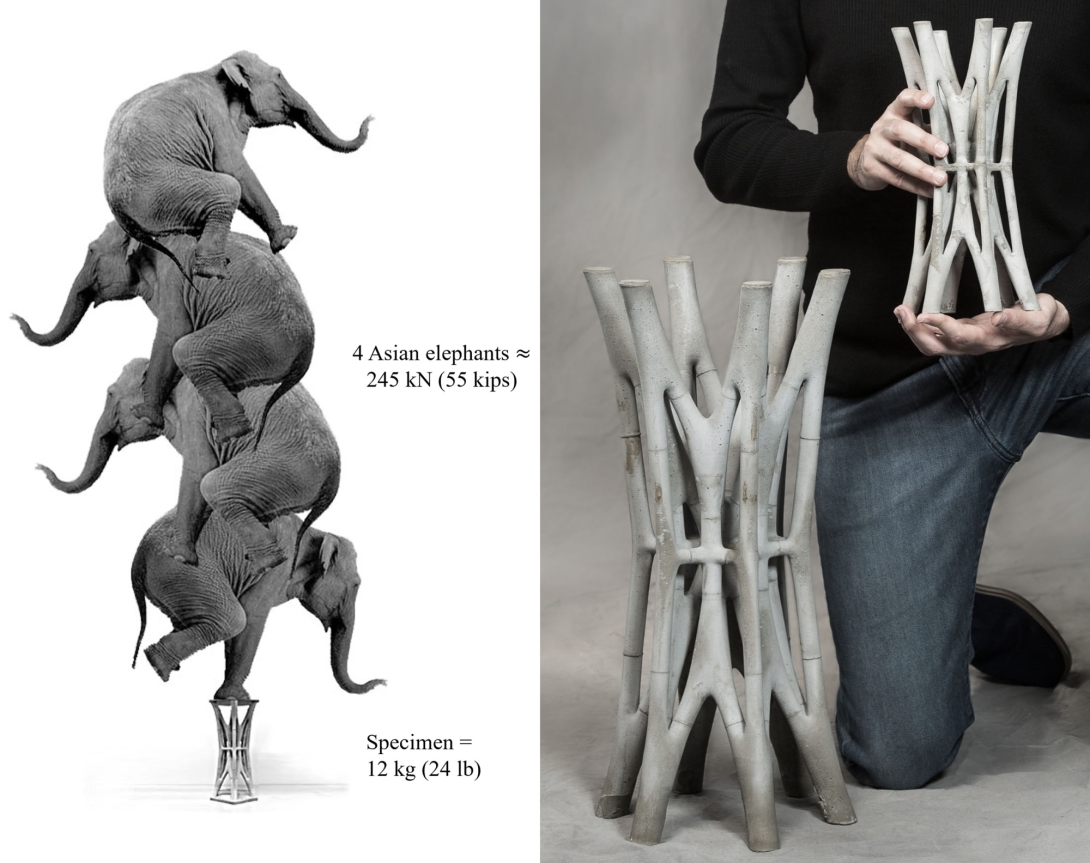
The 12 kg (26.45 lbs) specimen could take 240 kN load (2,000 times more than its self-weight).
Intuitive Design, Explicit Optimization, and Efficient Fabrication
Unlike any other structural design technique, a designer can design the geometry of the force diagram that guarantees the equilibrium of the resulting structural form. For instance, a designer can aggregate force polyhedrons and explore a variety of nonconventional spatial structural forms with minimum bending moments in their members. (25) Besides, since the areas of the polyhedral faces represent the magnitude of forces, the optimization criteria become entirely explicit and understandable. Further, the inherent planarity constraints between the form and force diagrams dictate that the resulting concepts include planar facets, making their construction much easier. Thus, polyhedral graphic statics can combine structural form-finding and fabrication optimization in a single method. Therefore, it opens a new horizon to an unexplored realm of efficient spatial structural solutions for prefab, lightweight, high-performance systems.
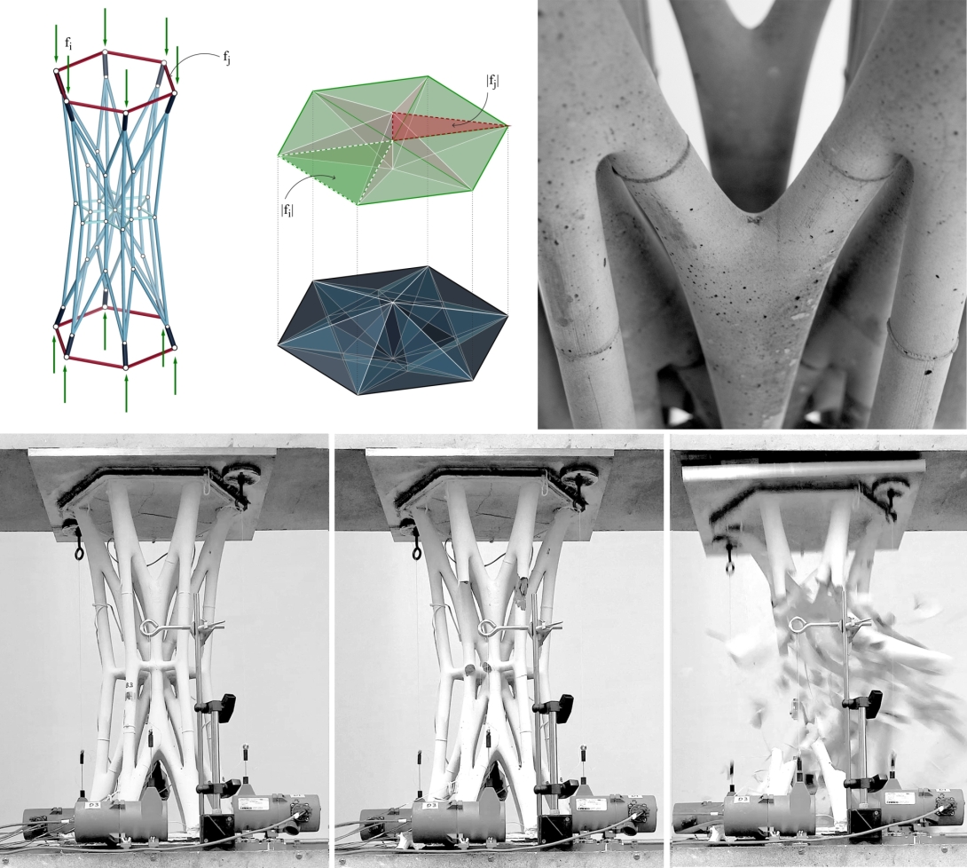
(a) to (c) form and force diagram for a cylindrical sample designed by using polyhedral graphic statics; and (d) to (f) the final compression-only prototype tested to failure.
A Valuable Teaching Tool
In an interactive environment, the reciprocal relationships between the form and force diagrams help students understand structural concepts more intuitively than ever. For instance, a designer can change the magnitude of the applied forces and observe the resulting change in the form of the structure and its internal forces. This property can teach students what parameters control their design and how they can deliberately modify those parameters to achieve specific design criteria, a feature that a few other existing structural design methods have.
1) D. Piker, “Kangaroo: Form finding with computational physics,” Architectural Design, vol. 83, no. 2, pp. 136–7, 2013.
2) A. Kilian and J. Ochsendorf, “Particle-spring systems for structural form finding,” Journal of the International Association for Shell and Spatial Structures, vol. 46, no. 2, pp. 77–85, 2005.
3) A. Kilian, “Cadenary tool v.1 [computer software].” www.designexplorer.net/project pages/cadenary.html, 2004 (Accessed March 1, 2009).
4) K. Linkwitz and H. J. Schek, “Einige Bemerkung von vorsgepannten Seilnetzkonstruktionen,” Ingenieur-Archiv, vol. 40, pp. 145–158, 1971.
5) H. J. Schek, “The force density method for form finding and computation of general networks,” Computer Methods in Applied Mechanics and Engineering, vol. 3, no. 1, pp. 115–134, 1974.
6) M. R. Barnes, “Form finding and analysis of tension structures by dynamic relaxation,” International Journal of Space Structures, vol. 14, no. 2, pp. 89–104, 1999.
7) S. Adriaenssens, P. Block, D. Veenendaal, and C. Williams, eds., Shell Structures for Architecture: Form Finding and Optimization. London: Taylor & Francis – Routledge, 2014.
8) E. Morsch, “Der eisenbetonbique, seine theorie undanwendung,” Reinforced Concrete, Theory and Application, Verlag Konrad Wittwer, Stuttgart, 1912.
9) T. J. Hughes, The Finite Element Method: Linear Static and Dynamic Finite Element Analysis. Lowell, MA: Courier Corporation, 2012.
10) J. Schlaich, K. Schäfer, and M. Jennewein, “Toward a consistent design of structural concrete,” PCI Journal, vol. 32, no. 3, pp. 74–150, 1987.
11) A. Muttoni, M. Fernández Ruiz, and F. Niketic, “Design versus assessment of concrete structures using stress fields and strut-and-tie models,” ACI Structural Journal, vol. 112, no. S49, pp. 605–616, 2015.
12) C. Meléndez, P. F. Miguel, and L. Pallarés, “A simplified approach for the ultimate limit state analysis of three-dimensional reinforced concrete elements,” Engineering Structures, vol. 123, pp. 330–340, 2016.
13) G. Meschke, B. Pichler, and J. G. Rots (eds.), Computational Modelling of Concrete Structures: Proceedings of the Conference on Computational Modelling of Concrete and Concrete Structures (EURO-C 2018), February 26–March 1, 2018, Bad Hofgastein, Austria. London: CRC Press, 2018.
14) M. P. Bendsøe, Topology Optimization. Berlin, Germany: Springer, 2009.
15) M. P. Bendsøe and O. Sigmund, “Material interpolation schemes in topology optimization,” Archive of Applied Mechanics, vol. 69, no. 9–10, pp. 635–654, 1999.
16) H. A. Eschenauer and N. Olhoff, “Topology optimization of continuum structures: A review,” Applied Mechanics Reviews, vol. 54, no. 4, pp. 331–390, 2001.
17) Q. Q. Liang, Y. M. Xie, and G. P. Steven, “Topology optimization of strut-and-tie models in reinforced concrete structures using an evolutionary procedure,” Structural Journal, vol. 97, no. 2, pp. 322–332, 2000.


